Some thoughts on Pimoroni’s “Pico GFX Pack” LCD module

I have in my home office a NAS (networked storage) device that I made from a Raspberry Pi 4 and a heap of high-capacity disk drives. It’s served me pretty well for many years, although I’ve had to replace and add drives. One thing it lacks, though, is a display. Of course, the Pi 4 has an HDMI video output, and I could plug any kind of display into it. I can also log into it remotely, and administer it that way. Still, it would be nice if it had a display that could tell me at a glance if, for example, there were any problems that needed immediate attention.
Now, I’m quite concerned about the amount of energy we’re wasting because of appliances we can’t switch off, and I’ve even started constructing USB power supplies with real mains switches. But my NAS runs twenty-four hours a day, so I’ve tined it to use as little power as practicable. I don’t want to add a big, colour display that will use more energy that the NAS itself. I’ve wanted for a while to add one of those monochrome LCDs that fancy scientific calculators have. They’re large enough to display about eight rows of 25-column text, but still only consume a couple of milliwatts.
For a long time I couldn’t find one that I could interface easily to a Raspberry Pi. I considered alternatives: alphanumeric LCD displays based on the HD4D780 are dirt cheap, and easy to interface – particularly the models with a built-in I2C interface. But the 2x16 and 2x20 units can’t show enough information, and the 4x20 units are too large. They all have poor contrast (more on this below), and need strong back-lighting to be usable.
An OLED display would also be a possibility. The problem with these is that the inexpensive ones are too small to hold much text, even though their comparatively high resolution makes for an elegant display. An OLED screen designed for a smartphone would be ideal, but way too expensive for this application.
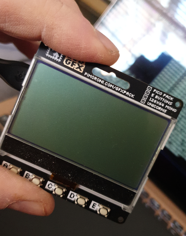
So I was pleased to come across Pimorono’s Pico GFX Pack. This unit has an 128x64 LCD module with integrated controller, mounted on a PCB that is socketed for a Rasberry Pi Pico microcontroller. My first idea was to repurpose this module to connect directly to a Raspberry Pi but, in fact, the Pico is inexpensive and, carefully programmed, requires only a few milliwatts of power. The Pico has a USB interface that can both power the unit, and also act as a serial communications interface. So I decided it would be interesting to make a self-contained display terminal based on the GFX Pack and some software I’d write myself. Another program on the Pi NAS collects diagnostic data, and sends it to the Pico over USB.
The source code for my Pico firmware is available in my GitHub
repository. If you’re interested in using this display, you might
find the source for the display driver useful (look for
st7567.cpp). I’ve put a lot of comments in, explaining how
the controller works, and how to drive it.
On the whole, I’m happy with the performance of the display, although it’s not perfect. So here are my thoughts on the Pimoroni GFX Pack.
Construction and layout
The GFX Pack is a module about 6cm x 6cm in area, and about 2cm tall with the Pico in its socket. The Pico USB socket is on the left so, if you’re using USB, you’ll need to allow some clearance to the left for the USB cable.
The PCB has 3mm holes in the corners for fitting mounting bolts. If you want the unit in an enclosure, you can make a panel cut-of the size of the LCD (and perhaps the buttons) and mount the whole assembly behind the panel. The light from the backlight bleeds out of the bezel surrounding the LCD though so, for best results, you’ll need to mount it very precisely, so that the whole of the LCD is visible, and none of the bezel. This requires painstaking measurement and cutting.
Below the display are five pushbuttons, connected to Pico GPIO pins. I don’t know how much use they’re likely to be, if you’re mounting the display in an enclosure. They’re handy for testing and prototyping, however. There’s also a ‘reset’ pushbutton on the back of the PCB.
On the right of the module, opposite the USB connection, is a 4-pole socket that connects to the Pico’s I2C pins. I don’t know if this socket is an industry-standard part, or something proprietary to Pimoroni products. I can see how it would be useful if you wanted to connect I2C sensors, particularly as none of the other GPIO pins are accessible. If you want to use any other GPIO pins, and don’t want to solder on the Pico (ugh!), you’ll need a breakout or adapter of some sort. More on this subject later.
Electrical interface
The ST7567 display controller in the LCD module supports several different parallel and serial interface standards, but the module is hard-wired to use clocked SPI. Although the display controller can be read, as well as written, by the microprocessor, the GFX Pack has no provision for that: the Pico’s SPI “MISO” pin isn’t connected to anything. I’ve not found much need to read these controllers, and I don’t see this as a significant omission. Pimoroni’s sample software clocks the SPI interface at 10MHz. I’ve tried faster clock speeds and they seem to work fine. However, at 10MHz the Pico can write the entire display in a few milliseconds, so I don’t see the point in using faster clock speeds.
The LCD module connects to the Pico’s SPI0 interface, and also to a GPIO pin for chip-select operations, a pin for command/data selection, and another for a hardware reset. GPIO pins are also allocated to the backlight LCDs and the pushbuttons. All in all, very few GPIOs are left over, so it’s perhaps no surprise that Pimoroni hasn’t provided any way to connect to them.
Some Pico peripherals, like SB Components’ real-time clock will mount between the Pico and the GFX Pack. This peripheral fits nicely, and works fine, because it only uses the I2C interface. You’d have to be quite careful with other Pico peripherals, even if the can physically be attached, because the chance of GPIOs clashing is quite high. There’s a circuit schematic on Pimoroni’s website, so it’s easy to check whether the GPIO pins you want to use are free. Probably they won’t be, given the number that the GFX Pack potentially uses.
Programming
The LCD module includes a Sitronix ST7567 display controller. This is easy to program (I’m using C++) and Pimoroni has some example code.
The ST7567 supports LCDs of up to 132x65 resolution (although the LCD fitted is only 128x64). The 65th row is reserved for ‘icons’. There are the little symbols that you often see around the main graphical display in commercial equipment. The ST7657 treats the ‘icon’ row differently to the main display rows, but that’s irrelevant here, as nothing’s connected to it.
The ST7567 divides the LCD display into ‘pages’ of 8 rows each. As the LCD has 128 columns, a page is effectively an 8x128 screen region. Each page can thus be considered a 128-byte memory block, given that there are 8 bits in a byte.
So far as I know, the display must be updated page-by-page: you can’t update a larger region than one page in a single SPI transfer. You can transfer part of a page but, in practice, I don’t see a need to: the transfer is so fast, and the amount of display memory so small, that it’s not efficient to try to work out which parts of a page need to be transmitted. In my application, I maintain an internal framebuffer the same size as the display memory, and synchronize every page that has been changed by a display operation. This is a lazy way to program a display, but it’s effective with this small display. With a higher resolution display, it might not even by possible to store a large enough framebuffer in the Pico’s tiny RAM.
The ST7567 controller accepts a range of 8-bit control codes, which are well-documented in the datasheet. The format of these codes is arcane: most use only part of the byte to identify the command, leaving the rest to carry a small data value. Because sometimes the data value won’t fit into the spare bits, a command will actually take two bytes, with a different part of the data in each. Some commands have a single bit of data, some more.
With the datasheet at hand, this kind of software interface is actually relatively easy to figure out, and learning how to program one controller will stand you in good stead for similar devices. For example, the ST7567 command set and programming method is essentially the same as that of the Sitronix ST7789, even though the latter controls a much larger, colour display.
To send a command byte, the procedure is:
- Set the data/command pin (GPIO 20) low, to indicate that we’re sending a command
- Set the chip select pin (GPIO 17) low, to activate the controller
- Write the byte to the Pico SPI using
spi_write_blocking() - wait 100 microseconds
- Set the chip select pin high.
To send pixel data, we first send the commands that set the page and
starting column to be written. In my application, the starting column is
always zero, as it always sends a whole page. Then we set chip select
low again. set the data/command pin high to indicate that we’re
sending data, not a command, and then send 128 bytes (a page) using
spi_write_blocking().
Before doing ths, the application must first initialize the ST7567. The way to do this depends on the characteristics of the LCD display panel, and the way it is wired to the ST7567. There’s no way to work this out, so far as I know, unless you have information from the manufacturer of the LCD module; but looking at Pimoroni’s sample software, in conjunction with the ST7567 datasheet, makes it clear. Before initializing, it’s as well to reset the ST7567 completely, by strobing the reset pin (connected to GPIO 21).
The fiddly part of drawing the display lies in the fact that the display memory has a mixture of row-ordering and column-ordering. If you’re used to working with Linux framebuffers, you’ll be familiar with the buffer data being organized in rows. That is, each row in the display corresponds to a bunch of bytes, with each byte holding data that represents a small part of the same row.
The ST7567, however – because it only needs one bit per pixel – uses each byte to represent a column of eight pixels on screen. But there’s still a byte for each column in a row. Once you have the logic to set a specific pixel at a specific point on or off, you can use that logic to build a display, regardless of the odd data ordering. However, in some instances it will be faster to build the display with the ST7567 in mind. For example, if you wanted to display an image, it’s probably faster to store the image data to match the way the ST7567 expects it, rather than doing a bunch of math to store every pixel.
Backlight
The GFX Pack provides three RGB LEDs and six white LEDs for backlighting. These four colours of LED are controlled by four GPIO pins – GPIO 6 to GPIO 9. In principle, you can set any backlight colour using combinations of red, green, and blue, but I don’t need this kind of cosmetic feature. The white LED is much clearer, to my eyes, than any combination of the red, green, and blue.
We can use PWM control to set the brightness of the backlight LEDs. This is easy with the Pico, as it has a built-in PWM controller. However, I find that if I need the backlight on, I need it at close to maximum brightness. In daylight, I find that the display is clear without the backlight, at a wide range of viewing angles.
Contrast issues
Driving an LCD display is hard. Each display pixel lies at the intersection of a row and a column, called a ‘common’ or a ‘backplane’, and a ‘segment’ in LCD jargon. So each common and segment control line will be affecting many different display pixels. But the average voltage applied to each pixel must be zero, or the display will eventually be damaged. So each row and segment line must be fed by a complex AC waveform. The display controller generates the appropriate waveforms, so the programmer doesn’t have to worry about it. However, this principle of LCD operation makes it hard to get great contrast. Anything that increases the darkness of the active pixels tends to increase the darkness of the inactive pixels as well.
To get the best overall contrast, we have to adjust the voltages applied to the pixels. The ST7567 has coarse and fine voltage adjustments. The coarse adjustment is called the ‘regulation ratio’ in the datasheet, while the fine adjustment is the ‘electronic volume’ (EV). The regulation ratio depends on the details of the LCD display, and I didn’t find much benefit in changing it. The EV can usefully be adjusted, in principle over the range 0-63. I found that values in the range 18-38 gave useable displays – I’m not sure if that will be the case for every unit. Pimoroni’s software sets this value to 30, but I found I got better contrast with a smaller value. In any case, an application will need to provide the user with a way to adjust the contrast, to suit the ambient light and viewing angle.
The photo below shows the display in use, with the best contrast I was able to achieve with a bit of fiddling.
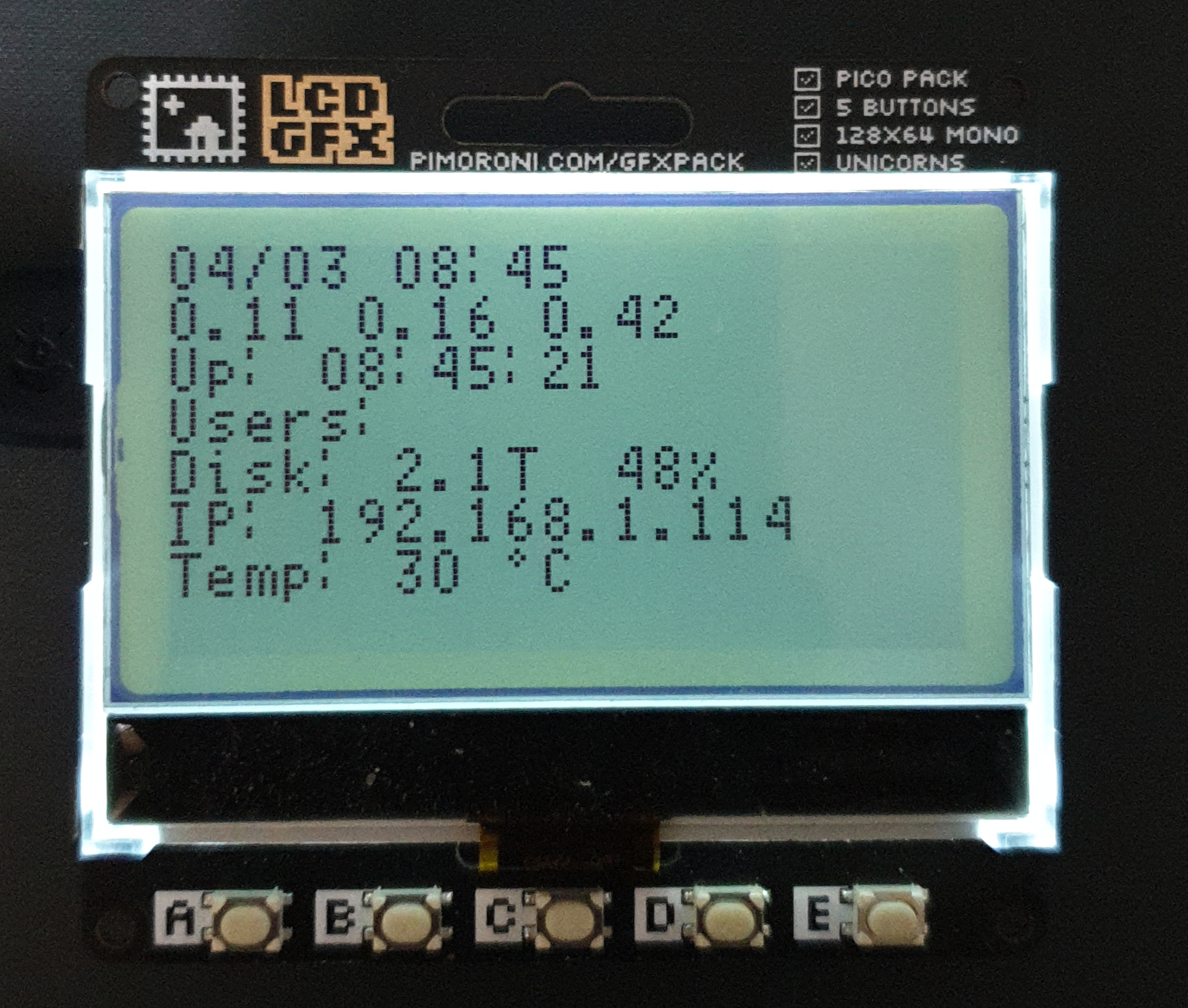
It’s not bad, but you can see that there’s some darkening of the background, which can’t be removed. The backlight (which as was on in the photo) improves the contrast in dim ambient light, but doesn’t make much difference in sunlight.
Closing remarks
The Pimoroni GFX Pack is an inexpensive, low-power mono display, with modest resolution. It’s relatively easy to program, as the low resolution means that there’s no need for complicated methods to determine exactly which part of the display needs to be updated. Contrast depends on the ambient condition and viewing angle, which means that any application will need to offer a way for the user to adjust it. It would be useful, and straightforward, to have the built-in pushbuttons do this, if they’re accessible.
The problem with the GFX Pack is that it uses nine GPIO pins for the five buttons and four different backlight colours. I’d be happy with one backlight, and I don’t really need the buttons (with the unit built into an enclosure). So I’d prefer a design that minimized the use of GPIOs, and made the unused ones more easily accessible.
Another problem – and it’s one that won’t affect everybody – is that the display is simply too small for my ageing eyes. I can make the text larger, but only by having less of it on screen. So, while the display works fine for my application. I remain in search of a larger one with a similar resolution. Or a magnifying lens that I can mount on top of it.
Have you posted something in response to this page?
Feel free to send a webmention
to notify me, giving the URL of the blog or page that refers to
this one.

